How to teach series and parallel circuits with one interactive demo
Start with a prediction, then change just one variable at a time. Students can see that series components share one current path, while parallel branches share source voltage and split the total current.
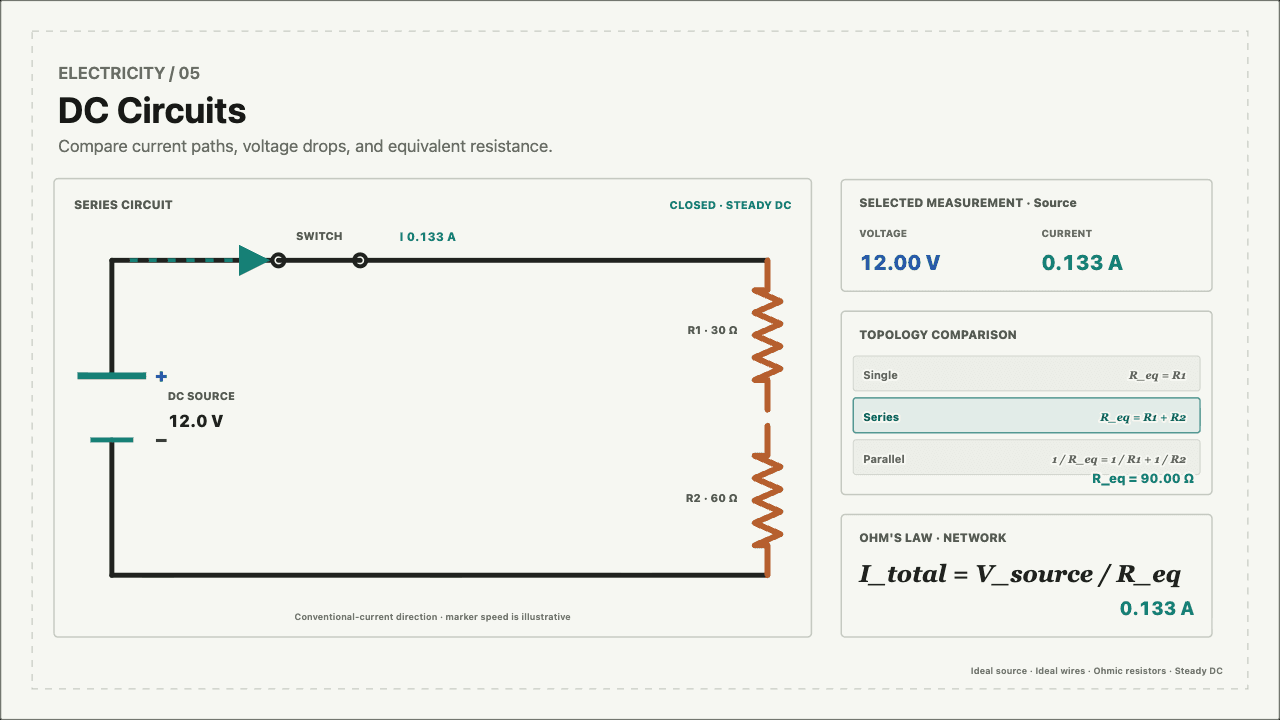
Students can predict and explain which quantities are shared, divided, or added in each circuit.
A short sequence with one visible question at a time.
- 1
Ask for a prediction
Show two identical lamps and ask: if one lamp is added, which circuit makes both lamps dimmer? Keep the answer hidden for now.
- 2
Build the series circuit
Set both resistors to the same value. Point to the single current path, then compare the current through R1 and R2 with the source current.
- 3
Switch to parallel
Keep the source voltage and both resistances unchanged. Show that each branch has the source voltage while the branch currents add at the source.
- 4
Change one resistor
Increase R2 only. Students should see the R2 branch current decrease while the R1 branch remains unchanged in the ideal parallel model.
- 5
Explain the result
Return to the prediction. Have students justify the difference using current paths, voltage, and equivalent resistance rather than brightness alone.
Listen for these explanations.
Current is used up
In a series circuit, current is the same at every component. Energy is transferred by the charges; the charge flow is not consumed.
Voltage is the same everywhere
Voltage is a difference between two points. In series it divides across components; in parallel each branch is connected across the same two source terminals.
A new parallel branch steals current
For an ideal voltage source, adding a parallel branch lowers equivalent resistance and increases total source current. An existing branch keeps the same voltage.
What the measurements should show.
Series
One path means the source current, R1 current, and R2 current are equal. The source voltage is the sum of the resistor voltage drops.
Parallel
Each branch has the source voltage. The source current is the sum of branch currents, so total current rises when another branch is added.
One resistor changes
With an ideal source, changing R2 in parallel changes only its branch current. It does not change the voltage across R1.
The demo uses ideal wires, an ideal DC source, and ohmic resistors.
That scope lets students isolate the circuit relationships before discussing non-ideal batteries, lamps, or heating effects. The series and parallel relationships in this guide follow OpenStax Physics 2e, 10.3: Resistors in Series and Parallel.
Run the comparison in the interactive circuit experiment.
Switch among single, series, and parallel topologies, then reveal the readings and equations as students explain their prediction.